
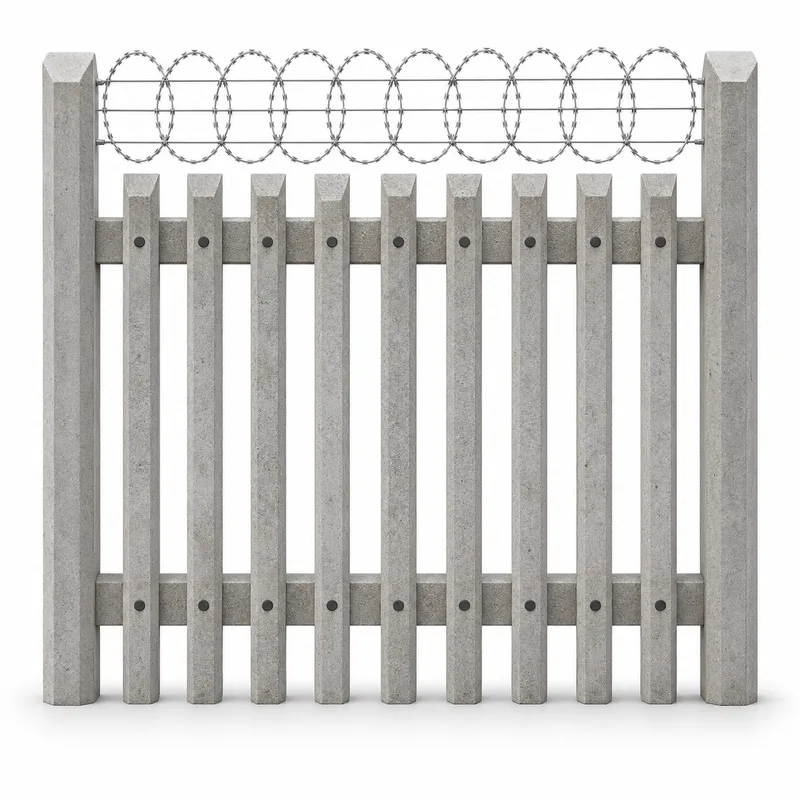
Nine reinforced pales per standard section.
Concrete palisade fencing technical system
Concrete palisade fencing specifications—made clear.
Realistic product visualization and controlled technical guidance for Capstone’s 1.8 m and 2.4 m reinforced concrete palisade assemblies, including razor-flatwrap options.
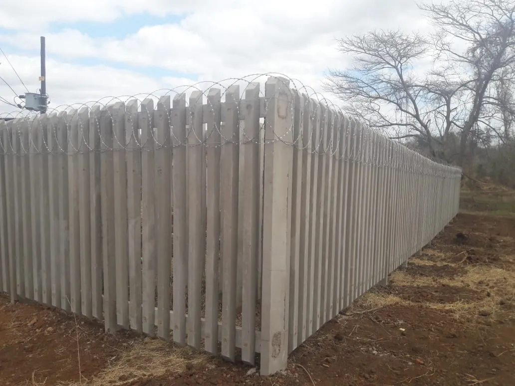
Product + controlled dimensions
See the reinforced bay, then read the specification.
The original specification drawing shows the standard section. Compare the supplied configuration drawings and the readable dimensions below.
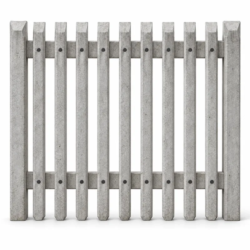 CP–R01 Original specification drawing
 Product referenceOriginal concrete palisade drawing
The supplied 1.8 m specification drawing shows the nine-pale, two-crossbar section. It is not to scale; use the dimensions and source documents below.
- 2 000 mm centres
- Exactly 9 pales
- 2 reinforced crossbars
- 1.8 / 2.4 m systems
CP–01Concrete palisade bay
Quotation-stage elevation · not for construction
FRONT ELEVATIONPost + crossbar + pale assembly
Reinforced concrete rails with nine 8 mm holes.
Top and bottom fixing for every pale.
Minimum 15 MPa concrete; final detail is site-specific.
CP / COMPONENTSReinforced concrete assembly
Component-level technical view
Inside the system
Designed as an assembly.
Each two-metre bay combines two posts, nine reinforced pales, two reinforced crossbars and top-and-bottom fixings.
Bay format2 000 mm post centres
Vertical members9 reinforced pales
Horizontal members2 reinforced crossbars
Fixings8 mm pale fixing bolts, top and bottom
Product strength20–34 MPa depending on curing period
Configuration matrix
Four documented systems.
Compare fence height, total post length and the razor-flatwrap option. The grid below replaces four near-illegible page thumbnails.
CP-18Standard system
CP-18
1.8 m standard
- Fence
- 1 800 mm
- Total post
- 2 400 mm
- Top detail
- No razor flatwrap
CP-18RRazor addition
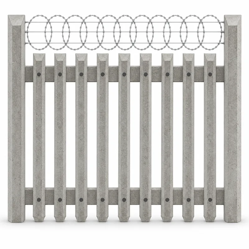
CP-18R
1.8 m + flatwrap
- Fence
- 1 800 mm
- Total post
- 2 900 mm
- Top detail
- 500 mm flatwrap
CP-24Standard system
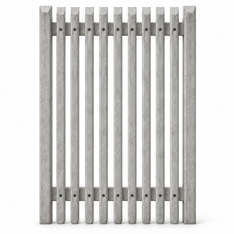
CP-24
2.4 m standard
- Fence
- 2 400 mm
- Total post
- 3 000 mm
- Top detail
- No razor flatwrap
CP-24RRazor addition
CP-24R
2.4 m + flatwrap
- Fence
- 2 400 mm
- Total post
- 3 600 mm
- Top detail
- 500 mm flatwrap
CP / SITE DETAIL
Foundation + security detail Download isometric source drawing
What happens below and above the fence.
The supplied drawing records a quotation-stage foundation and optional security arrangement. Final footing, ground condition, loading and statutory requirements are project-specific.
01Standard foundation450 × 450 × 600 mm deep; minimum 15 MPa concrete
02Optional baseOptional 200 × 150 mm concrete plinth
03Razor addition500 mm razor flatwrap with 2.24 mm straining wires
04Extended supportExtended support post at 4 m intervals shown on flatwrap drawing
Specification control
From standard detail to site-specific solution.
The diagrams explain Capstone’s supplied source sheets. Final post lengths, foundations, concrete, loads, ground conditions, slopes, services, razor requirements and statutory compliance are defined for the actual project.
Project enquiry
Need a concrete palisade system and quote?
Send the selected height, approximate metres, razor or plinth requirement, project location, gates and any tender or engineer specification.